


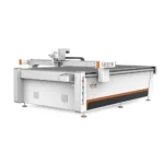
CNC Oscillating Knife Cutting Machine for PET Panels – Industrial Application
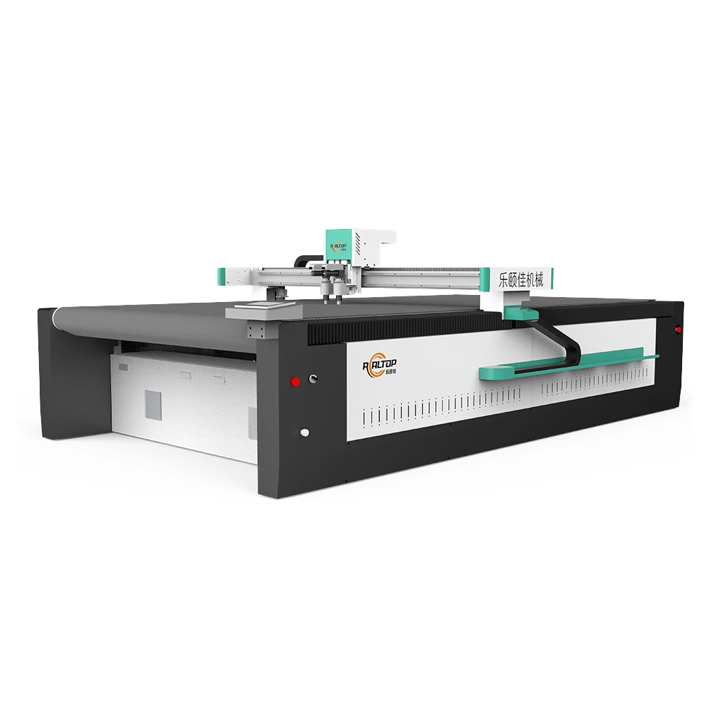
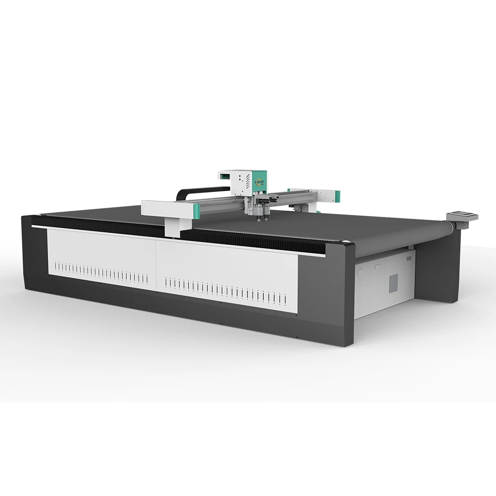
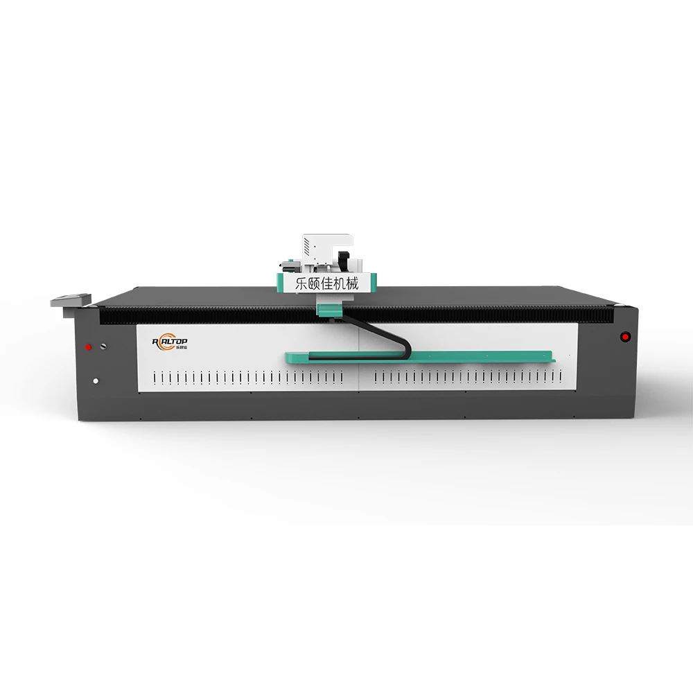
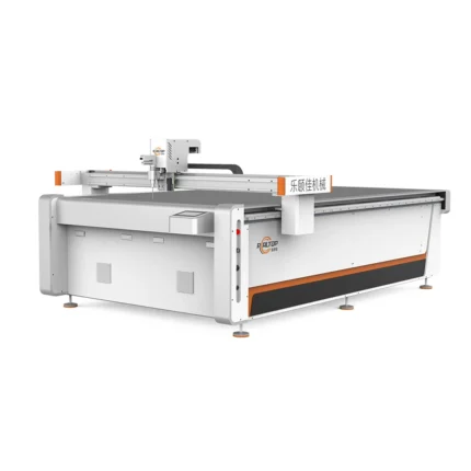
CNC Oscillating Knife Cutting Machine for PET Panels, 1600×2500mm Working Area, ±0.1mm Accuracy — engineered for composite material processing without thermal damage to resin systems. High-frequency oscillating knife delivers clean cuts on PET panels, carbon fiber prepreg, and aramid honeycomb cores with no delamination or fraying. Interchangeable tool heads adapt to soft fiberglass cloth and rigid G10 epoxy boards. Cold cutting process preserves structural integrity where laser power specifications fall short. Sample cutting validation on buyer-specific composite materials before order confirmation, with tool head configuration matched to material thickness and production workflow.
Cold Cutting Precision — Oscillating knife technology preserves resin integrity in composite panels without the thermal degradation typical of laser processing on carbon fiber and aramid honeycomb structures.
Technical Specifications
| Parameter | Value |
|---|---|
| Product Type | CNC Oscillating Knife Cutting Machine |
| Working Area | 1600×2500 mm |
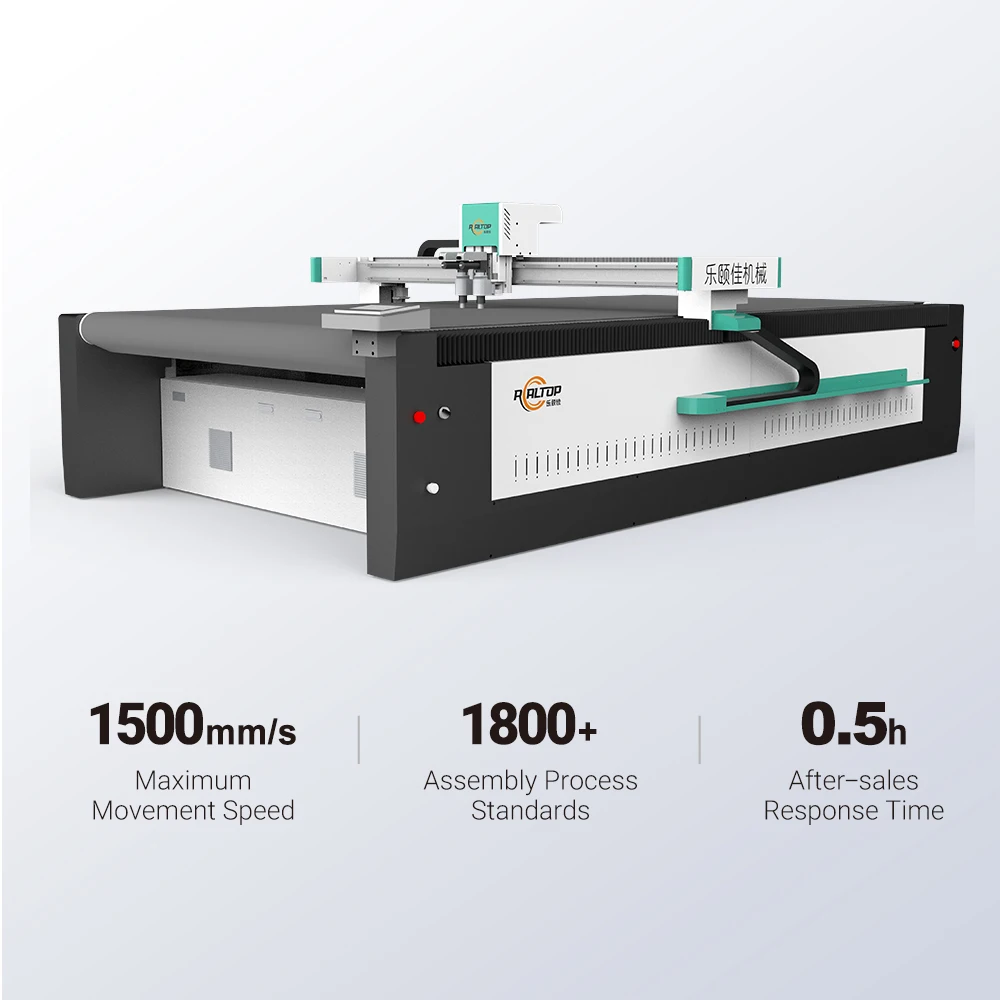
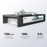
| Cutting Speed | 0-2000 mm/s |
| Cutting Thickness | ≤ 30 mm |
| Cutting Accuracy | ±0.1 mm |
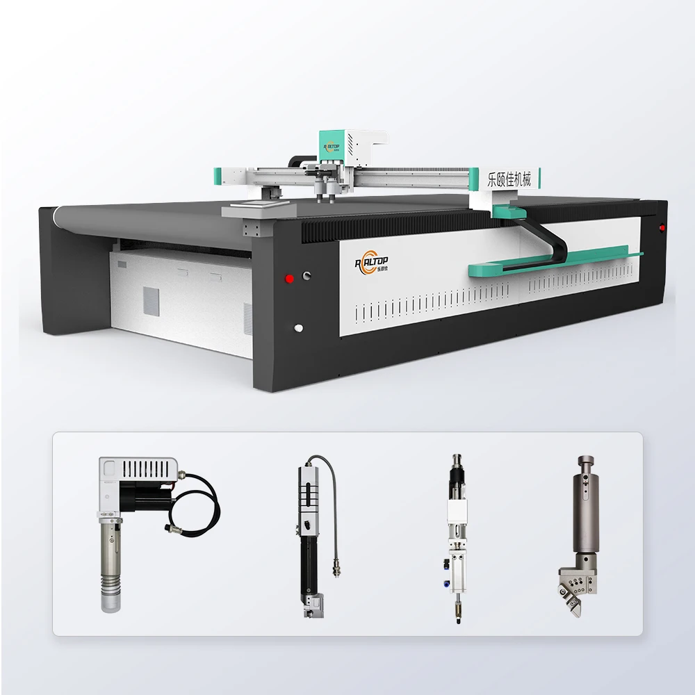
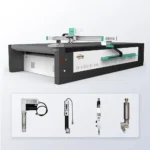
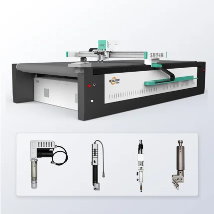
| Tool Options | Oscillating knife, Driven rotary knife, Creasing wheel, Kiss cutting tool, Pneumatic knife, Milling tool, V groove knife |
| Vacuum Pump | 9 kW |
| Vacuum Table | Aluminum bellows vacuum table |
| Control System | PLC control panel |
| Servo Motors | Panasonic, Delta, Dorna options |
| Machine Frame | Heavy-duty frame with precision-ground surface |
| Voltage | Configurable for 110V, 220V, 380V |
| Safety Features | Infrared sensor device and emergency stop |
| File Compatibility | PLT, DXF, AI, PDF |
| Language Options | English, Russian, Italian, Chinese (customizable) |
| Machine Size | 3300×2100×1350 mm |
Application Suitability
| Application | Material or Output |
|---|---|
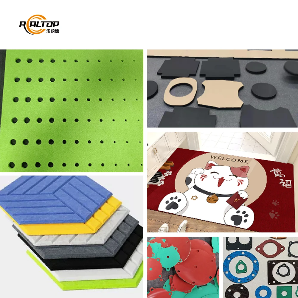
| Aerospace Component Fabrication | Carbon fiber prepreg, aramid honeycomb (Nomex) cores, fiberglass cloth, ceramic fiber blankets, thermal and acoustic insulation foam |
| Wind Turbine Blade Production | Fiberglass cloth, carbon fiber cloth, vacuum infusion mesh, PET and PVC foam core materials |
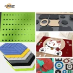
| Automotive Interior Manufacturing | Acoustic felt, damping pads, composite trim panels, carpets, sealing strips, lightweight body panels, battery insulation sheets |
| Sporting Goods Manufacturing | Carbon fiber sheets and fabric, fiberglass, Kevlar, high-performance foam for bicycle frames, helmet liners, surfboards |
Why Peak Power Ratings Fail on Composite Laminates
Physical blade contact removes the thermal variable entirely from the cutting equation.
Many composite processors have experienced the frustration of specifying a thermal cutting system based on quoted peak output, only to discover the continuous cutting capacity falls short when processing multi-layer carbon fiber prepreg or dense aramid honeycomb cores. The resin matrix in composite materials responds unpredictably to heat input, creating delamination risks and edge degradation that compromise structural certification. An oscillating knife cutting approach eliminates thermal influence altogether, producing clean mechanical separation through high-frequency blade vibration rather than material vaporization. [NEED_CITE: thermal degradation mechanisms in carbon fiber reinforced polymer cutting]
Eliminating Thermal Damage in Resin Systems
The fundamental advantage of cold cutting for composite fabrication lies in preserving the chemical bond between fiber reinforcement and resin matrix. When processing materials like G10 epoxy boards or carbon fiber laminates, excessive heat input causes the resin to soften, smear, or carbonize along the cut edge. The CNC oscillating knife cutting machine for composites operates through rapid mechanical oscillation, separating fibers cleanly without altering the resin cure state. This matters critically for aerospace components where edge integrity directly affects bonding surface preparation for secondary assembly operations.
High-Frequency Oscillation Mechanics
The oscillating knife tool head vibrates at frequencies sufficient to slice through dense composite structures without generating friction heat or requiring excessive downward force. This vibration frequency prevents the blade from dragging or catching on directional fiber orientations common in carbon fiber cloth and fiberglass weaves. The result is a cut edge free from fraying, burr formation, or delamination between plies. For aramid honeycomb cores used in aircraft interior panels, this mechanical action crushes neither the cell walls nor the node bonds that provide structural rigidity. [NEED_CITE: oscillation frequency specifications for composite cutting tool heads]
Matching Tool Geometry to Composite Density
Different composite materials demand specific blade profiles and oscillation parameters. The available tool range addresses this variation: oscillating knife heads handle rigid panels up to the thickness capacity, while driven rotary knife options suit flexible materials like fiberglass cloth and insulation blankets. The pneumatic knife option provides additional downward force capability for dense carbon fiber boards. The V groove knife enables precise scoring operations for fold-line creation in sandwich panel construction. Selection depends on material density, fiber orientation, and whether the cutting operation requires through-cut or kiss-cut depth control.
The Cost of Ignoring Material-Specific Configuration
Selecting a cutting system without first verifying tool head compatibility with your specific composite formulation leads to production losses that compound across every shift. Ragged edges on carbon fiber parts require secondary finishing operations that were never budgeted. Delaminated honeycomb cores get rejected at quality inspection, wasting both material and machine time. Vacuum table zoning configured for large sheets fails to hold small aerospace brackets during cutting, causing lift and dimensional drift. These failures appear gradually, often attributed to operator error rather than fundamental equipment mismatch. [NEED_CITE: composite cutting defect classification and root cause analysis]
Manufacturing Capability Verification
In-house design and production covering both knife and laser cutting technologies means composite processors can match cutting method to material behavior rather than forcing one approach across all applications. Tool head and table configurations get specified per material type and production volume before order confirmation. CCD camera positioning options exist for printed contour work on pre-printed composite sheets. Software compatibility with nesting workflows gets confirmed through file format verification. Voltage and control language customization happens before shipment rather than after arrival. Sample cutting on buyer-supplied composite material provides physical evidence of cutting quality before commitment.
Documentation & Verification
- Sample cutting report generated on your specific composite material and thickness before purchase commitment
- Tool head configuration list matched to your material portfolio from carbon fiber to aramid honeycomb
- Electrical schematic confirming voltage, frequency, and circuit requirements for your facility
- Software license documentation with confirmed compatibility for PLT, DXF, AI, and PDF nesting workflows
- Factory test record documenting cutting accuracy verification on representative composite samples
- CE declaration documentation for European market compliance where applicable
Installation, Commissioning & Support
- Heavy-duty frame requires level concrete substrate capable of supporting the machine footprint and dynamic cutting loads
- 9 kW vacuum pump demands dedicated electrical circuit separate from control system power
- Machine arrives partially assembled requiring rigging and positioning within your facility clearance envelope
- Initial commissioning includes vacuum table zoning configuration matched to your typical part geometries
- Operator training covers tool head changeover procedures across your composite material range
- Spare parts inventory recommendation based on blade consumption rates for your specific materials
Requesting a Technical Proposal
Composite cutting applications require specific material data to generate accurate equipment recommendations. Provide sample material including type designation, actual measured thickness, and any existing nesting file formats you currently use. Specify your local electrical supply voltage and frequency, plus preferred control panel language for operators. Indicate whether your production workflow involves pre-printed materials requiring optical contour recognition or if you work exclusively from digital cutting files.
Frequently Asked Questions
Q: How do you verify cutting quality on composite materials without thermal damage?
A: We perform sample cutting on your actual composite material before any purchase commitment. This produces physical cut samples you can examine for edge quality, delamination, fiber fraying, and dimensional accuracy. The sample report documents cutting parameters used, tool head configuration, and achieved tolerances. You evaluate the results against your quality standards before proceeding.
Q: Which tool head configuration works for carbon fiber versus aramid honeycomb?
A: Carbon fiber boards typically require oscillating knife or pneumatic knife tools depending on thickness and density. Aramid honeycomb cores respond better to specific oscillating knife profiles that cut cell walls without crushing the honeycomb structure. We recommend tool head selection based on sample cutting results from your specific material variants.
Q: Can voltage and control language be customized for different regional markets?
A: The system supports voltage configuration for 110V, 220V, or 380V supplies with appropriate frequency matching. Control panel language options include English, Russian, Italian, and Chinese, with additional languages configurable based on your operator requirements. All electrical documentation reflects your confirmed specifications before shipment.
Q: What file format compatibility exists for aerospace CAD workflows?
A: The control system accepts PLT, DXF, AI, and PDF formats directly. We verify file compatibility with your existing nesting software during the quotation phase. If your workflow uses proprietary aerospace industry formats, we confirm conversion compatibility before order confirmation.
Q: What are the material thickness limits and how is cutting accuracy verified?
A: The system handles composite materials up to 30mm thickness depending on material density and tool head selection. Cutting accuracy of ±0.1mm gets verified during factory testing on your sample materials. The test record documents actual achieved dimensions across multiple cut samples from your material batch.


Related products
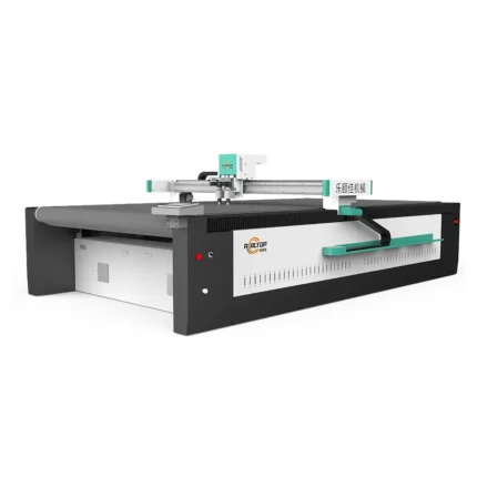

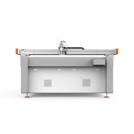

2516 CNC Vibrating Knife Cutting Machine 2026
Product Introduction
2516 CNC Vibrating Knife Cutting Machine 2026, a precision cutting solution from China's leading welding & cutting equipment manufacturer. Ideal for efficient, high-quality material processing with advanced CNC technology.
Key Specifications
| Model | 2516 |
| Type | CNC Vibrating Knife Cutting Machine |
| Year | 2026 |
| Origin | China |
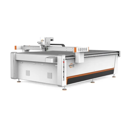
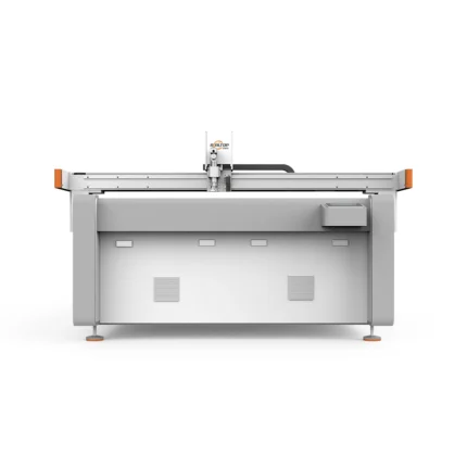
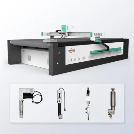
Acoustic Panels CNC Knife Cutting Machine 2026
Product Introduction
Designed for precision cutting of acoustic panels, this 2026 CNC knife cutting machine offers efficient and accurate processing, ideal for acoustic panel manufacturers seeking high-quality results.Product Parameters
| Model | Acoustic Panels CNC Knife Cutting Machine 2026 |
| Application | Acoustic Panels Cutting |
| Type | CNC Knife Cutting Machine |
| Year | 2026 |
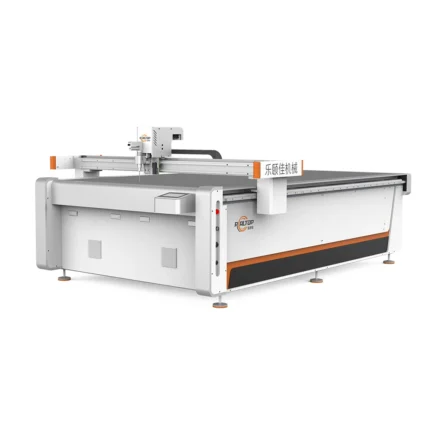
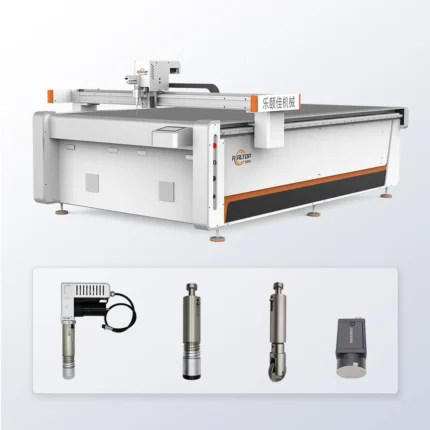
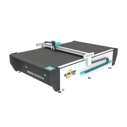
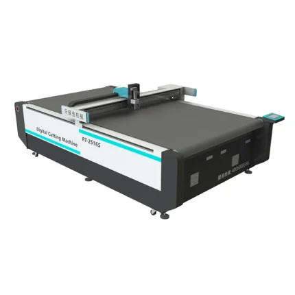
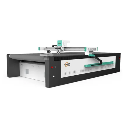
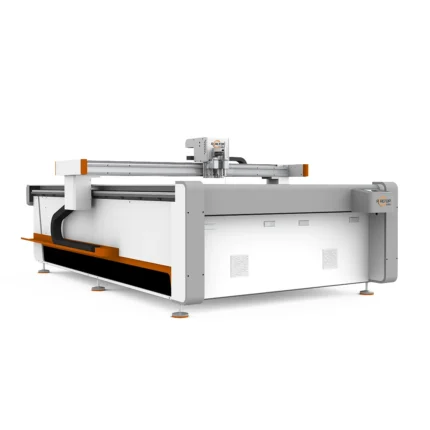
Realtop CNC Felt Panel Cutter 2026 Auto Digital Flatbed PET Cutter
Product Introduction
Realtop CNC Felt Panel Cutter 2026 is an auto digital flatbed designed for precise cutting of PET acoustic sheets, ideal for efficient and accurate fabrication in acoustic panel production.Key Specifications
| Model | Realtop CNC Felt Panel Cutter 2026 |
| Type | Auto Digital Flatbed Cutter |
| Application | PET Acoustic Sheets |
| Function | Precision Cutting |
商品评价
There are no reviews yet.