


Composites CNC Cutting Machine for Foam – Laser Process Guide
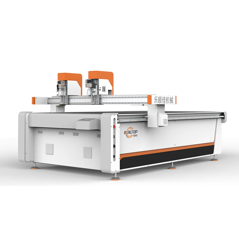
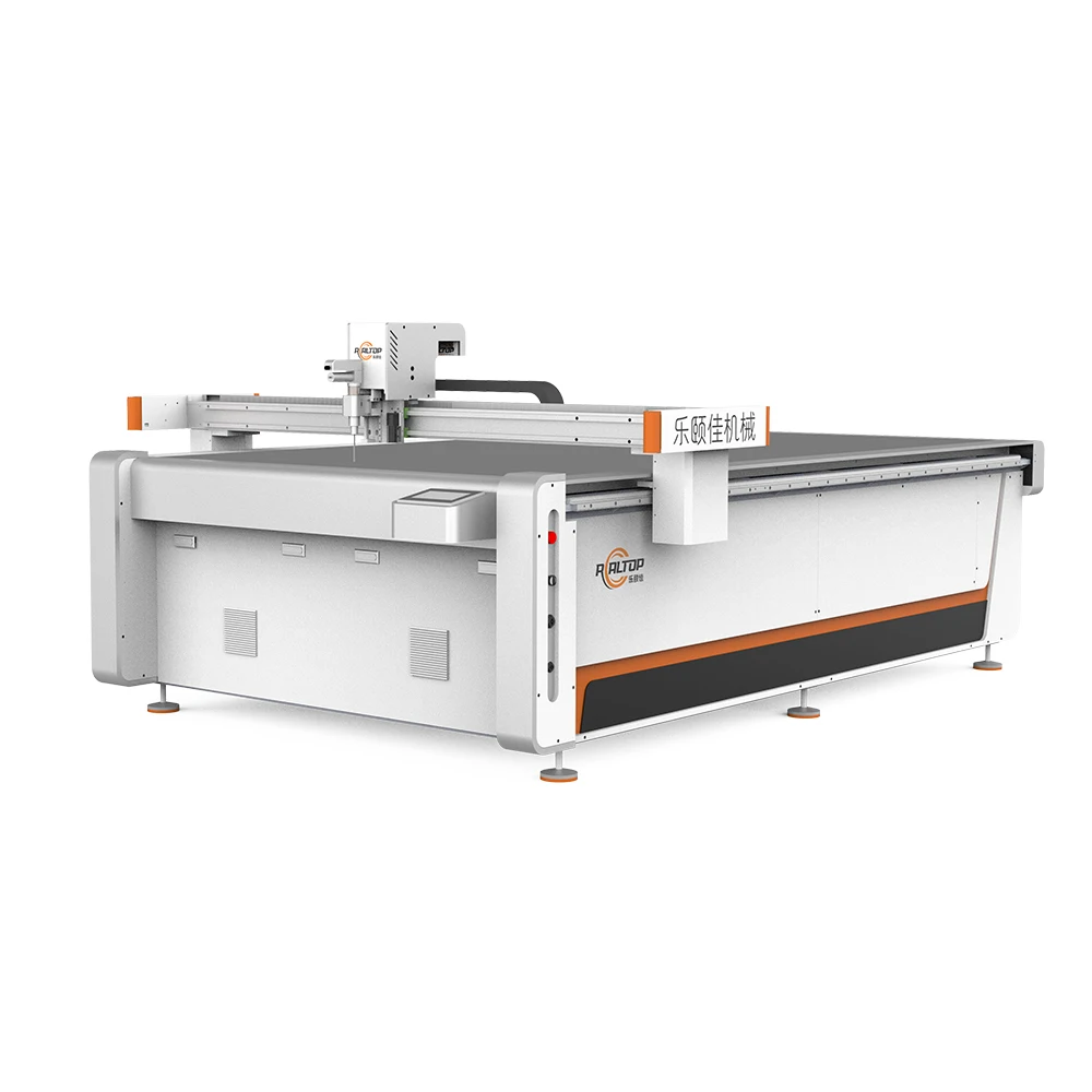
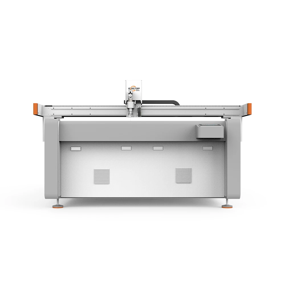
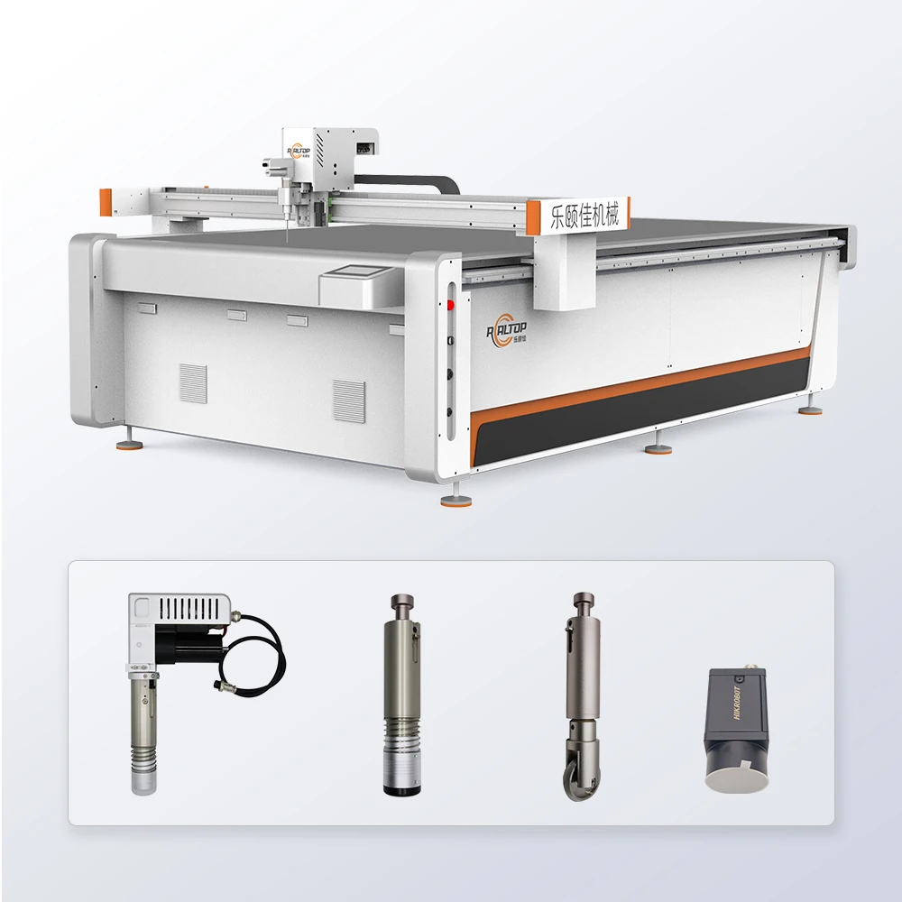
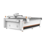
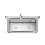
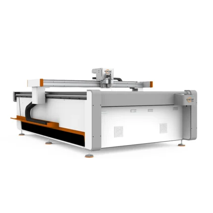
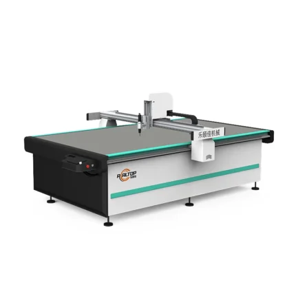
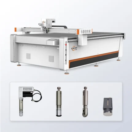
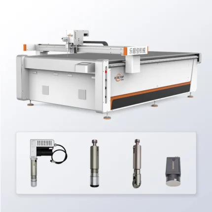
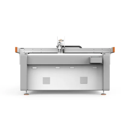
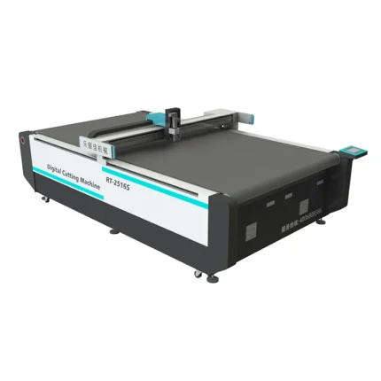
RT-D2516/RT-S2516 CNC Oscillating Knife Cutting Machine, 1600×2500mm Working Area, 380V, Swiss Imported Multi-Tool Head — engineered for composite, foam and flexible material processing with precision contour tracking.
- CO2 versus fiber laser comparison guides buyers toward the right thermal process, while this oscillating knife system delivers clean physical blade cuts with no heat-affected zone on foam and composites.
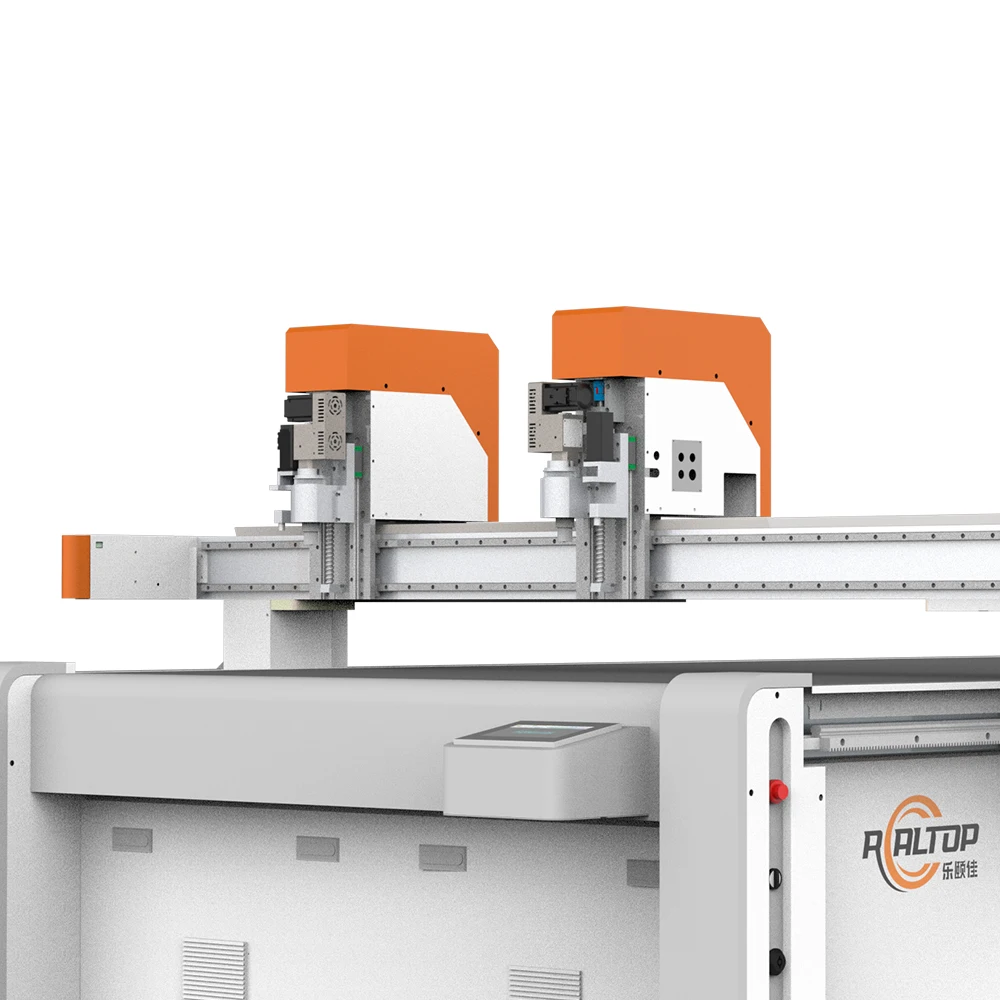
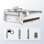
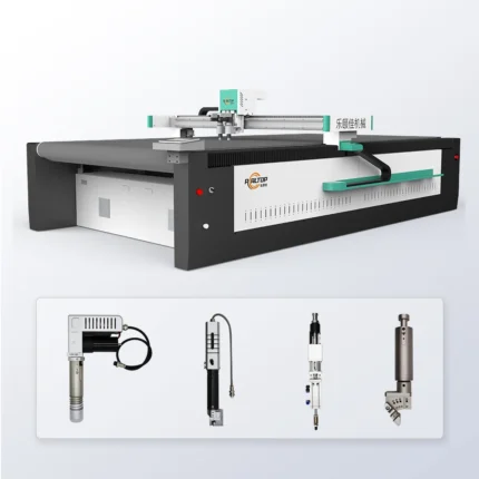
- Tool head matched to material thickness and type — oscillating knife, pneumatic knife, drag knife and creasing wheel among 10+ options, with CCD camera positioning for printed contour recognition at production speed.
- Magnesium-aluminum vacuum table with zoned adsorption holds small parts flat, paired with Delta/Panasonic servo drives and Taiwan Hiwin guides for ≤0.1mm repeatability.
Sample cutting on your own material before commitment, with full configuration list, electrical schematic and voltage confirmation matched to your facility.
Voltage customization confirmed — electrical schematics validated against your local grid standards before production begins, eliminating on-site rewiring delays.
Technical Specifications
| Parameter | Value |
|---|---|
| Model | RT-D2516/RT-S2516 |
| Working Area | 1600×2500mm |
| Machine Dimensions (L×W×H) | 3450×2300×1250mm |
| Rated Power | 9kW |
| Operating Voltage | 380V±10% (configurable) |
| Cutting Speed | 800-2000mm/s |
| Repeatability | ≤0.1mm |
| Transmission System | Digital servo motor (Delta or Panasonic optional), Taiwan Hiwin linear guide |
| Multifunctional Head | Swiss imported oscillating knife with vibration full/half cutting |
| Tool Head Options | Oscillating knife, pneumatic knife, high-power vibrating knife, circular knife, drag knife, creasing wheel, punching, brush |
| Vacuum Table | Magnesium-aluminum alloy with PVDF coating and zoned adsorption |
| Vacuum Pump | 7.5kW with integrated silencer |
| Visual Positioning | Small CCD mark point, panoramic camera recognition, projection positioning |
| Control System | CNC with HP-GL compatible format |
| Safety Features | Infrared induction blocking, anti-collision, emergency stop |
| Certification | CE declaration where applicable |
Application Suitability
| Application | Material or Output |
|---|---|
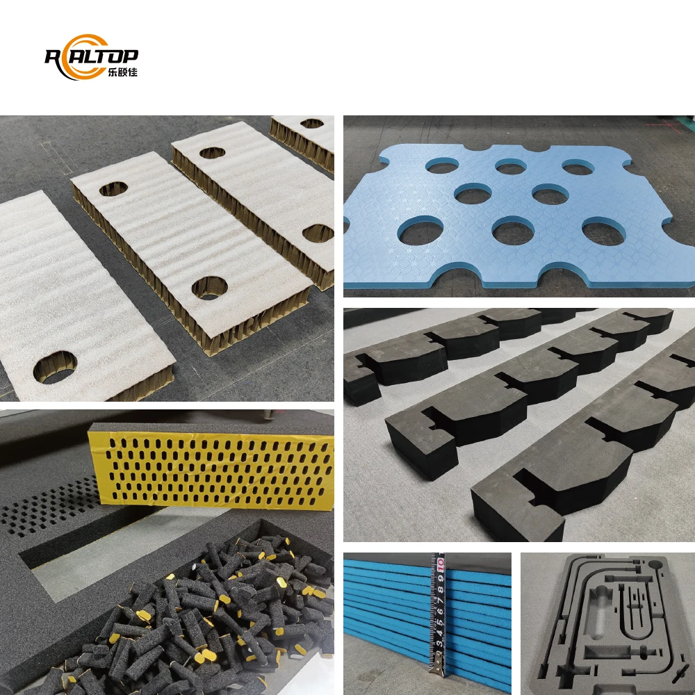
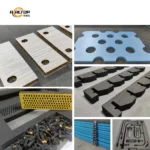
| Automotive interior trimming | Composite foam panels, sound insulation materials, dashboard substrates |
| Gasket fabrication | Rubber sheets, silicone compounds, non-asbestos fiber materials |
| Footwear and leather goods | Sponge composite leather, synthetic textiles, EVA foam layers |
| Packaging sample making | Corrugated board, folding carton stock, foam inserts |
| Signage production | PVC foam board, acrylic sheets, vinyl graphics on rigid substrates |
Why Material Thickness Claims Fail in Production
Cutting capacity depends on material density and tool configuration, not just blade stroke length.
Buyers often see thickness ranges quoted without the material context that determines actual performance. A machine cutting 20mm low-density foam behaves differently than one processing 20mm compressed gasket fiber. The oscillating knife frequency, blade geometry and vacuum hold-down pressure all shift based on what you’re actually running [NEED_CITE: material density impact on cutting tool selection].
The CNC Oscillating Knife Cutting Machine addresses this through tool head matching — Swiss imported oscillating knives for clean foam edges, high-power vibrating knives for dense composites, pneumatic options for thick rubber. Each configuration gets tested on your actual material before the machine ships.
Tool Head Selection Determines Edge Quality
The multi-tool platform lets you match the cutting method to the material rather than forcing one approach across different jobs. Oscillating knives produce clean, uncompressed edges on foam and sponge composites where drag knives would crush the surface layer. Creasing wheels handle fold lines on packaging samples without cutting through, while punching tools create holes and cutouts in a single operation.
Visual Positioning for Printed Contour Work
CCD camera positioning tracks printed registration marks on pre-printed materials, enabling contour cutting of graphics on composite panels or fabric. The panoramic recognition system captures the entire sheet layout, while the small CCD mark point camera handles high-speed tracking on continuous production runs [NEED_CITE: CCD positioning accuracy standards for digital cutting].
How Drive Precision Translates to Production Results
The Delta or Panasonic servo motors paired with Taiwan Hiwin linear guides achieve ≤0.1mm repeatability across the full 1600×2500mm working area. This matters when cutting interlocking gasket patterns or nested automotive interior pieces where accumulated error across multiple cuts causes assembly problems downstream. The synchronous belt and ball screw transmission maintains positional accuracy regardless of where the tool head sits on the table.
The magnesium-aluminum vacuum table with zoned adsorption solves a specific problem: small parts lifting during cutting. When you’re processing nested layouts with intricate contours, insufficient vacuum in specific zones causes material shift that ruins the piece [NEED_CITE: vacuum table zoning requirements for small part cutting]. The PVDF coating prevents adhesive residue buildup from composite materials.
The Hidden Cost of Wrong Configuration Choices
Selecting a machine based on working area alone leads to problems when your material thickness exceeds what the standard tool head handles. A buyer who specified for 1600×2500mm table size but didn’t confirm cutting depth capacity for 50mm EVA composite ended up with ragged edges and crushed material layers. The tool head must match both material type and thickness range.
Voltage mismatches discovered after delivery mean production delays while transformers get sourced or wiring gets redone. The 380V±10% baseline works for many markets, but confirming your local grid specifications before production prevents on-site electrical work [NEED_CITE: industrial voltage standards by region].
Why Source Through This Channel
The manufacturer handles both knife and laser cutting technologies in-house, so you get a cutting method recommendation based on your material rather than a forced solution. Tool head and table configurations get specified per your material samples, not generic catalog defaults.
Software compatibility gets confirmed before the order — your existing file formats and nesting workflows must import correctly. Sample cutting runs on your actual production material, with edge quality and cutting speed documented in the report you receive before commitment. Voltage, plug type and control language customization happen during production, not as field modifications.
Documentation & Verification
- Electrical schematic with voltage and frequency confirmed for your facility before production
- Tool head and table configuration list matching each tool to specific material types and thicknesses
- Sample cutting report on your actual material documenting edge quality, cutting speed and tool wear
- Factory test record showing repeatability measurement across the full working area before dispatch
- Software license and file format compatibility note confirming your existing workflow imports correctly
- CE declaration documentation where applicable to your market requirements
Installation, Commissioning & Support
- Machine dimensions 3450×2300×1250mm require floor space assessment and access path planning before delivery
- 380V±10% power supply needs dedicated circuit with proper grounding and phase confirmation on-site
- Vacuum pump 7.5kW operates with integrated silencer, but exhaust routing may be needed in enclosed spaces
- First power-on includes servo calibration, vacuum zone testing and tool head offset verification
- Operator training covers tool change procedures, vacuum zoning setup and CCD camera calibration
- Spare parts list includes oscillating knife blades, vacuum seals and drive belt specifications
- Maintenance schedule covers linear guide lubrication, belt tension checks and vacuum filter replacement
Moving Forward with Your Project
Send material samples representing your actual production stock — different batches or densities require separate testing. Specify your daily volume targets, typical sheet sizes and the contour complexity you’re cutting. Confirm your facility voltage, frequency and the control language your operators need. If you have existing nesting software or file formats, provide sample files for compatibility verification before the order goes to production.
Frequently Asked Questions
Q: How do you verify cutting capacity for our specific composite material?
A: We run sample cutting tests on your actual production material before the order is finalized. The test documents cutting speed, edge quality and tool wear across your thickness range. Different material densities require different tool configurations, so we need physical samples rather than just specifications.
Q: What accuracy can we expect from the CCD camera positioning system?
A: The system tracks printed registration marks for contour cutting, but accuracy depends on mark quality, contrast and size. We test the camera recognition on your actual printed materials at production speed to verify it maintains tracking without manual intervention during runs.
Q: Which tool head should we choose for our mixed material production?
A: Tool selection depends on material type, thickness and edge quality requirements. Oscillating knives work for foam and soft composites, high-power vibrating knives handle dense materials, and creasing wheels create fold lines without cutting through. We specify based on your sample testing results.
Q: Can the voltage and control interface be customized for our market?
A: Yes. Voltage, plug type, frequency and control language get confirmed and customized during production. We provide electrical schematics showing the final configuration before the machine ships, so you know exactly what arrives at your facility.


Related products

2026 High-Speed Rubber Sheet Cutter 120m/min CNC
Product Introduction
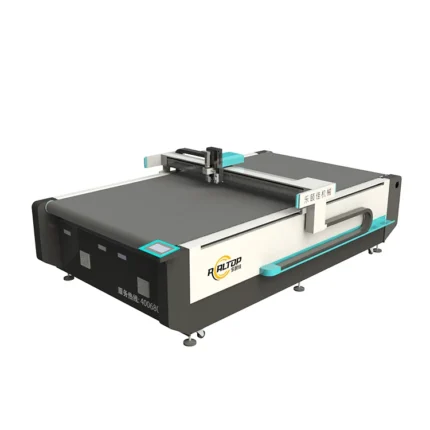
2026 High-Speed Rubber Sheet Cutter is a CNC composite cutting machine designed for efficient cutting operations, ideal for rubber sheets and composite materials with high precision and speed.
Product Parameters
| Cutting Speed | 120m/min |
| Control System | CNC |
| Application | Rubber Sheets, Composite Materials |

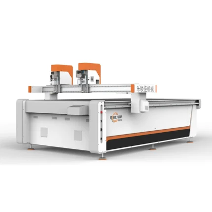
2026 Oscillating Knife Foam Insert Digital Packaging Cutter
Product Introduction
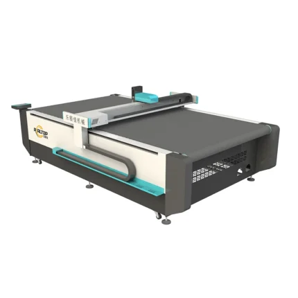
Designed for foam insert cutting, this 2026 Digital Packaging Cutter features oscillating knife technology, ideal for precise digital packaging applications with efficient cutting performance.Product Parameters
| Parameter | Details |
|---|---|
| Type | Oscillating Knife Cutting Machine |
| Application | Foam Insert Cutting |
| Model Year | 2026 |
| Category | Digital Packaging Cutter |

CNC Gasket Cutting Machine 2026 Digital Rubber Cutter High-Precision
Product Introduction
High-precision CNC gasket cutting machine with digital control, ideal for rubber materials. Features auto table operation for efficient, accurate cutting in industrial applications.
Key Specifications
| Type | CNC Gasket Cutting Machine |
| Function | Digital Rubber Cutter |
| Precision | High-Precision |
| Operation | Auto Table |
| Model Year | 2026 |
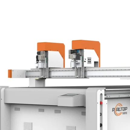
Jinan Realtop CNC Foam Cutting Machine 2026
Product Introduction
Jinan Realtop CNC Foam Cutting Machine 2026, a high-precision solution from China's leading welding & cutting equipment manufacturer, ideal for efficient foam cutting applications with reliable performance and advanced CNC technology.Key Specifications
| Model | 2026 |
| Type | CNC Foam Cutting Machine |
| Manufacturer | Jinan Realtop |
| Origin | China |

Realtop CNC 2026 Carbon Fiber Glass Mat CE Cutting Machine
Product Introduction
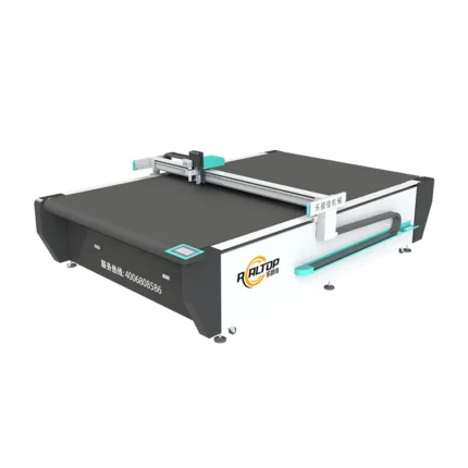
High-performance Realtop CNC Cutting Machine 2026, ideal for carbon fiber and glass mat cutting. CE certified for quality and safety, perfect for precision manufacturing needs.
Key Specifications
| Material Compatibility | Carbon Fiber, Glass Mat |
| Certification | CE Certified |
| Type | CNC Cutting Machine |
| Model | 2026 |
商品评价
There are no reviews yet.