

Blog
Fiber Laser Marker Space Planning for Aerospace Cutting OEM Manufacturer

Fiber Laser Marker Space Planning for Aerospace Cutting OEM Manufacturer
The machine footprint is a lie.
Effective space planning for fiber laser markers in aerospace goes beyond the physical dimensions of the unit; it requires integrating exhaust infrastructure, safety exclusion zones, and material flow dynamics to prevent operational bottlenecks. Most facility managers allocate space based on the manufacturer’s datasheet, only to find their production cell choked by ducting requirements and restricted operator access during high-mix composite processing.
I learned this the hard way not in a cleanroom, but in the sweltering heat of Apapa port in Lagos. I spent weeks watching a shipment of oscillating knife cutters sit idle because the packing list didn’t align with the HS code. The delay wasn’t just about paperwork; it was a lesson in how specifications dictate reality. When those machines finally reached an automotive interior supplier, the real challenge began: fitting them into a line that hadn’t accounted for the vibration isolation pads or the air compressor proximity. That experience shaped my approach to fiber laser marker space planning. It isn’t a drawing exercise; it is the difference between a cell that runs smoothly and one that becomes a permanent bottleneck.
Why Does Machine Footprint Mislead Aerospace Planners?
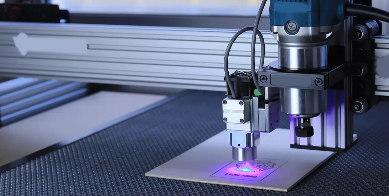
The visible unit represents only a fraction of the spatial requirement. When you look at a fiber laser marker, you see a compact box. What you don’t see is the ecosystem it demands to operate safely and efficiently within an aerospace manufacturing environment.
In aerospace, precision is non-negotiable. A carbon fiber wing component or a fuselage panel requires marking that is legible, permanent, and compliant with traceability standards. However, the assumption that the laser marker can be placed wherever there is empty floor space is a critical error. The actual usable footprint is dictated by maintenance access, thermal management, and safety interlocks.
Consider the maintenance zone. Technicians need clear access to the rear and sides of the unit for lens cleaning, galvo head adjustments, and fiber optic inspections. If you place the marker against a wall or too close to a neighboring CNC table, you force a complete shutdown of the adjacent equipment every time routine maintenance is required. This creates a hidden cost in downtime that far exceeds the value of the saved floor space. [NEED_CITE: ISO 11553 safety standards for laser machinery maintenance access]
Furthermore, the base stability matters. Aerospace composites are often marked on large, heavy fixtures. The vibration from nearby oscillating knife cutters or milling machines can affect the focusing accuracy of the laser if the mounting surfaces are not isolated. In my observations, facilities that treat the laser marker as an isolated island rather than part of a dynamic cellular layout often face recurring focus drift issues.
How Do Exhaust and Cooling Systems Dictate Layout?
Infrastructure needs often exceed the machine’s physical dimensions. This is particularly true when marking aerospace composites like carbon fiber reinforced polymers (CFRP) or fiberglass. The ablation process generates fine particulate matter and potentially hazardous fumes that must be captured immediately.
Many planners underestimate the volume of the exhaust ducting required. It is not enough to have a vent nearby; the duct diameter and airflow velocity must meet specific criteria to ensure effective capture without creating turbulence that could disturb the laser beam or the workpiece. [NEED_CITE: Occupational health regulations for laser fume extraction efficiency]
In high-ceiling hangars or older industrial buildings, routing these ducts can be a logistical nightmare. I once consulted for a facility where the laser marker was installed directly under a structural beam. The exhaust duct had to make three sharp turns to reach the main ventilation shaft. The resulting backpressure reduced the extraction efficiency significantly, leading to visible residue buildup on the protective window of the laser head. This required frequent cleaning and increased the risk of beam attenuation.
Chiller placement is another overlooked factor. Fiber lasers generate heat that must be dissipated to maintain wavelength stability and power consistency. The chiller unit itself has a footprint, requires airflow for its own condensers, and needs water line connections. If the chiller is placed too far from the laser, the length of the water lines can introduce pressure drops and potential leak points. Conversely, placing it too close can raise the ambient temperature around the laser electronics, triggering thermal shutdowns.
| Infrastructure Component | Spatial Impact | Planning Consideration |
|---|---|---|
| Laser Marker Base | Minimal | Ensure vibration isolation from nearby cutting tools |
| Exhaust Ducting | High | Direct path preferred; avoid sharp bends to maintain airflow velocity |
| Chiller Unit | Moderate | Requires ambient airflow and proximity to minimize water line length |
| Electrical Cabinet | Low | Needs clearance for door swing and cable management |
What Is the Optimal Flow Between Cutting and Marking?
Minimizing handling distance reduces damage risk for delicate aerospace composites. In a typical aerospace production cell, parts move from raw material storage to cutting, then to marking, and finally to inspection or assembly. The transition between cutting and marking is a critical touchpoint.
For manufacturers using oscillating knife cutters for soft composites, gaskets, or interior panels, the integration with a fiber laser marker can streamline the workflow. The key is positioning. If the laser marker is located too far from the cutting table, operators must transport parts across the factory floor, increasing the risk of contamination, edge damage, or misidentification.
However, "closer is better" is not always true. Insufficient safety buffering between a high-speed oscillating knife cutter and a laser marker can cause operational conflicts. The noise and vibration from the cutter can interfere with the laser’s sensitive optics. Moreover, if both machines share a common emergency stop zone without proper segmentation, a minor issue on one machine can halt the entire cell.
A better approach is to create a dedicated marking station that acts as a buffer. Parts are transferred from the cutting table to a staging area, then moved to the laser marker. This allows for quality checks before marking, ensuring that only good parts are processed. For high-mix, low-volume production, this setup also facilitates faster changeovers. Operators can prepare the next job on the laser while the current part is being cut, or vice versa.
At Realtop, we see this synergy frequently. Our oscillating knife cutters are often positioned adjacent to laser markers in customer facilities. By leveraging shared CAD/CAM data, the transition from cutting to tracing or marking becomes seamless. The digital file drives the cutting path, and the same coordinate system can guide the laser marking process, reducing setup time and eliminating manual alignment errors. This integration is a core benefit of thoughtful fiber laser marker space planning.
Which Safety Zones Are Non-Negotiable?
Compliance with laser safety classes determines mandatory exclusion zones. Aerospace manufacturing environments are busy, with multiple operators, automated guided vehicles (AGVs), and overhead cranes operating in close proximity. A fiber laser marker, typically a Class 1 or Class 4 device depending on the enclosure and power, requires strict adherence to safety protocols.
The primary concern is eye safety. Even with enclosed systems, there are risks during loading and unloading if the interlocks are bypassed or if the enclosure is open for maintenance. Therefore, a designated safety zone must be established around the marker. This zone should be clearly marked with floor tape and signage, indicating that only authorized personnel wearing appropriate laser safety eyewear are permitted inside during operation. [NEED_CITE: IEC 60825-1 standard for laser safety classification and zoning]
Another critical aspect is the reflection hazard. Aerospace components often involve metallic surfaces or reflective composites. The laser beam can reflect off these surfaces, posing a risk to operators standing outside the immediate enclosure. Proper shielding and beam stops must be integrated into the layout. This may require additional space around the marker to install protective curtains or barriers.
Fire safety is also paramount. While fiber lasers are generally safer than CO2 lasers in terms of fire risk, marking certain composites can still generate heat spikes. The area around the marker should be kept clear of flammable materials, and fire suppression systems must be accessible. In some cases, local regulations may require a specific distance between the laser marker and other heat-generating equipment.
Ignoring these safety zones can lead to regulatory fines, insurance issues, and most importantly, worker injury. It is not just about compliance; it is about creating a culture of safety that supports efficient production. A well-planned safety zone allows operators to work confidently, knowing that the risks are managed and controlled.
Conclusion
Space is a strategic resource, not just empty floor.
Successful integration of a fiber laser marker into an aerospace production line requires a holistic view that encompasses exhaust, cooling, material flow, and safety. By looking beyond the machine footprint and considering the entire ecosystem, manufacturers can avoid costly bottlenecks and ensure smooth, compliant operations. Effective fiber laser marker space planning transforms a potential constraint into a competitive advantage, enabling higher throughput and better quality control in the demanding aerospace sector.

